|
|
Post by fredvv44 on Jun 6, 2012 19:31:36 GMT -5
you don't want to shorten the steering arms. the tie rods should be in a straight line across the car. i'm going through this same thing with my JZR 3w build. there is nothing wrong with the R&P in the front as long as the steer arms point the the rear wheel as you say. the next issue will be the height of the steer arm so as to eliminate bump steer. you really need to address that issue. the "wishbone" program is great for sorting all this out. Fred V I read an article regarding the ackerman issue and I now see what is out of sorts. I responded in the long and lengthy post 2 up as far as what I can try to do to fix it. I was under the assumption..........that if I was using all Mustang II suspension stuff then I couldn't possibly be that far off and I was unfortunately wrong. I know I can't swap the spindles around and resolve the issue. It would actually make it worse than what it currently is now because it would push the line further to the outside end of the axle. Keeping the steering knuckle up front is what I am going to have to do. I will either shorten the A arms to bring the line back in to the center where it belongs or I will bend the a arms to shorten the length of them. I still have to reinforce them anyway and I knew I wasn't done with them but now I know for certain that they definitely need to be shorter. I will also need to lengthen my Push rod to the shock as a result if I bend them but they already need to be longer anyway since they are maxed out on their length adjustment. I want to get the front end up on it anyway to at least 8-10 inches. Right now it is sitting around 5 1/2 which is too close for comfort. The back is going to ride somewhere near the 8 inch mark anyway with a level rear swing arm. Again Thanks everyone for the input. I really appreciate it. I want the thing to be right so I will correct it. |
|
|
|
Post by mtntech on Jun 7, 2012 2:38:43 GMT -5
Fred, He is going to shorten the A arms, not the steering arms on the spindle. Because he is using Mustang 2 spindles, he found out that things aren't lining up very well as far as Ackerman angles are concerned. I measured my M2 spindles and they are at about 5 degrees. As far as bump steer is concerned, determine the mounting height of the rack after you have everything else where you want it.
|
|
|
|
Post by mtntech on Jun 7, 2012 18:58:18 GMT -5
I just finished doing the calculations in regards to Ackerman geometry using the Mustang 2 spindles. To achieve true Ackerman with these spindles, the wheelbase of the vehicle has to be 6.5X the distance of kingpin to kingpin center. So if you have 5 feet from kingpin to kingpin (The rotational axis of the spindle, in this case basically the bottom balljoint), the wheelbase would have to be 32.5 feet long. Obviously these spindles were not engineered to follow the Ackerman principle, even in stock form. I wouldn't try to narrow your front end because it won't make any difference.
|
|
|
|
Post by joeld0803 on Jun 7, 2012 20:52:01 GMT -5
As it stands right now My front end is too wide anyway. Outside edge of the tire to the opposite tire is 7'2" which is wider than my full size GMC pickup wheel base.
I am planning on shortening the a arms to at least bring the front width down to no more than 6'8".
If I move the kingpin on the spindle in about 2"-3" on each side this will help reduce the amount of Pro ackerman I have but it might not get rid of all of it.
Any amount I can reduce it will help my tires on the wear factor.
I did some calculations myself based on the distance of the wheel base set points and the current angle I am facing on the ackerman issue.
As I mentioned if I run a straight line through my steering knuckle and lower kingpin on the spindle toward the center of my axle I am falling close to the center distance between my wheel and true center of my axle although slightly closer to the center of the axle.
I am not certain if moving the spindles in 2-3 inches will get it right or not but it will still at least reduce the width in the front.
As I mentioned earlier I can also possibly heat up the steering knuckle and slightly bend it outward which will sharpen the angle of my ackerman line towards the center of the axle.
Some articles talk about using pro ackerman in steering but my main concern is of course the tire wear and if I can reduce it some then that will be better than none.
I never planned to shorten the rack and pinion arm. The fact is I already built 2 - 14 inch extentions to thread onto the rods on each side just to get the rack to reach each side at the spindle. Apparently the front spindles are really close together on a mustang II as it is stock. They would have to be around 3 1/2- 4 feet apart. Mine came in at 6 feet 2 inches apart which is why my ackerman is way off.
|
|
|
|
Post by joeld0803 on Jun 7, 2012 20:54:37 GMT -5
Right now my steering arms are almost level but they do have a slight downward tilt.
|
|
|
|
Post by joeld0803 on Jun 7, 2012 21:00:20 GMT -5
Here is the front end angle of it 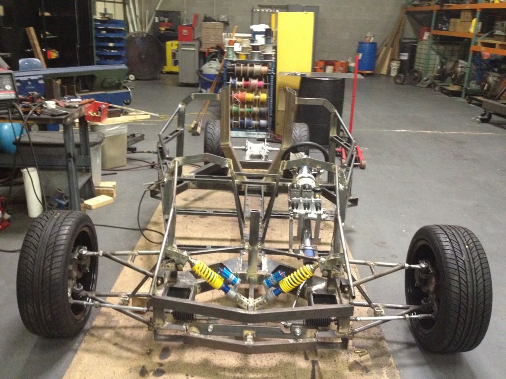 You can see where the boots from the rack stop and the original thread for the tierod ball joint is about 2" further than the end of the boot. The rest of what is sticking out there and actually going to the spindle arm are my extentions I made. I will have to shorten them as well if I shorten the a arms but I feel it is my only choice at this point. |
|
|
|
Post by fredvv44 on Jun 8, 2012 8:21:51 GMT -5
here is a good article on bump steer and how the R&P relates to the a-arms etc. www.circletrack.com/chassistech/ctrp_1001_bump_steer_explained/photo_02.htmlit looks like your inner rack ends are inside the a-arm pivots. this will do funny things to your steering. i highly recommend using a suspension geometry program to assist in designing the front end. it will allow you to find problems before welding everything up. interesting build. Fred V Here is the front end angle of it  You can see where the boots from the rack stop and the original thread for the tierod ball joint is about 2" further than the end of the boot. The rest of what is sticking out there and actually going to the spindle arm are my extentions I made. I will have to shorten them as well if I shorten the a arms but I feel it is my only choice at this point. |
|
|
|
Post by joeld0803 on Jun 8, 2012 10:13:26 GMT -5
All this info helps so thank you. At the rate this thing is being reviewed I'll be redoing the entire front end. At least I had the caster and camber adjustable and it was correct. I should hAve known it couldn't be that simple. Yea it's cool looking but all screwed up apparently. I like a challenge but now I am wondering where does one start to figuring the steering geometry into a project width all that has be achieved. Looking at the upper control Arm on that link you sent.......it is really short so in reality when a arms go up in a bump wouldn't that pull in on the upper part of the tire and throw out the camber and cause Inside tire wear as well. Just seems to me that there will never be perfect angles on everything all the time unless it is parked
|
|
|
|
Post by mtntech on Jun 8, 2012 10:14:46 GMT -5
What's your wheelbase? Are you using 2" drop spindles?
|
|
|
|
Post by joeld0803 on Jun 8, 2012 10:45:09 GMT -5
Yes they are 2 inch drop spindles. Is this intersecting centerline for the bump steer issue supposed to be at the center of the rack or what because they don't really Ellaborate. My spindle to spindle wheel base is 6'2". Outside of tire to outside of tire on the front is 7'2"
|
|
|
|
Post by mtntech on Jun 8, 2012 14:26:05 GMT -5
By wheelbase I meant front to rear. Not sure about the bump steer.
|
|
|
|
Post by joeld0803 on Jun 8, 2012 14:41:59 GMT -5
9 feet almost exactlly give or take 1/2 inch from center of tire to center of tire front to back
|
|
|
|
Post by joeld0803 on Jun 8, 2012 15:48:13 GMT -5
OK so here is the mustang II front suspension and it apaers to have the same geometry as mine as far as bump steer with the exception that the upper a arm is much smaller than mine. 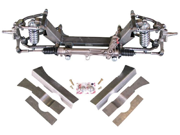 From what it looks like......True ackerman could be achieved since the tie rod ends are more or less 4 feet apart on the stock set up. |
|
|
|
Post by jim99 on Jun 8, 2012 21:48:43 GMT -5
Hi Joel,
When you shorten the A-Frames move the ball joint (rod end) inboard as close as possible to the intersection of the two tubes of the A-Frame.
The current A-Frames will fail where the straight section meets the intersection of the two tubes of the A-Frame. At speed that could prove to be deadly.
Jim
|
|
|
|
Post by joeld0803 on Jun 9, 2012 19:02:53 GMT -5
The upper ball joint on the upper a arm is threaded and almost 3" threaded up into the tube. The tube .120 thick. It isn't just welded at the end. I still plan on getting it as close as possible when I redo them. I also still plan on reinforcing the pointed end as well.
|
|
|
|
Post by fredvv44 on Jun 11, 2012 7:55:20 GMT -5
Joel, the front suspension is a total system and all elements must be designed to work together. if you use a M2 suspension it must be installed just as it was in the car. if you change one element it will affect the others.
several elements have been changed with your build. the wheelbase is shorter, the track width is wider and the R&P is shorter in relation to the a-arm pivots. all this adds up to it not working as it should. it is all fixable but will require some design time.
i'll mention one other thing i spotted. the shock mount on the lower a-arm should be as far out by the ball joint as is possible. the new Morgan 3W has theirs inboard like yours and i've seen a pic of the lower arm bent right at the shock mount. i believe they corrected it by using stronger tubing.
Fred V
|
|
|
|
Post by mtntech on Jun 13, 2012 1:22:06 GMT -5
The current A-Frames will fail where the straight section meets the intersection of the two tubes of the A-Frame. At speed that could prove to be deadly. Jim If it fails it will most likely be due to the forces exerted on that area of the A arm during braking. |
|
|
|
Post by joeld0803 on Jun 19, 2012 20:15:24 GMT -5
So I shortened the upper and lower control arms on both sides and reinforced the tubes and I am pretty certain it isn't coming apart the way its all welded together atrt the tip. The upper and lower ball joints are from a Dodge 3/4 ton pick up steering knuckle and they are about 9/16 of an inch and fine threaded and threaded up into the tube about 2 inches deep and locked up with a lock nut so I can at least adjust the upper. The width is now approx 6'8" which is better than 7'2" wide. It also reduced the bump steer issue and reduced the pro ackerman to some degree. I still may need to tweak the steering arm on the spindle a little to make it even better but it none the less is an improvement. I also got the rear shocks mounted and I now have a rolling chasis at least. Here are the recents 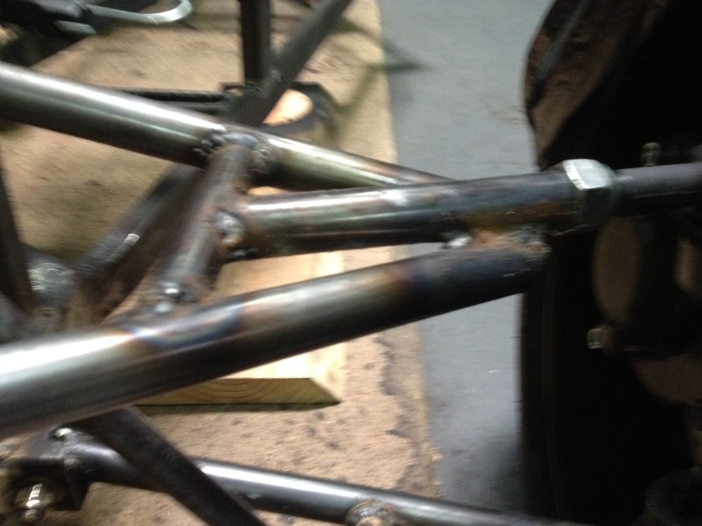 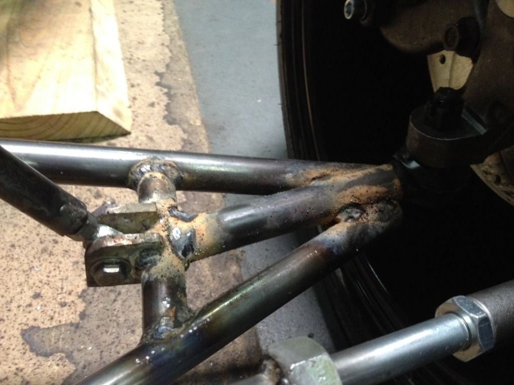 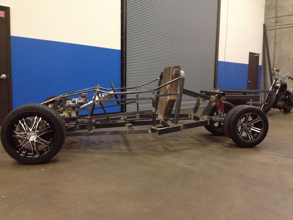 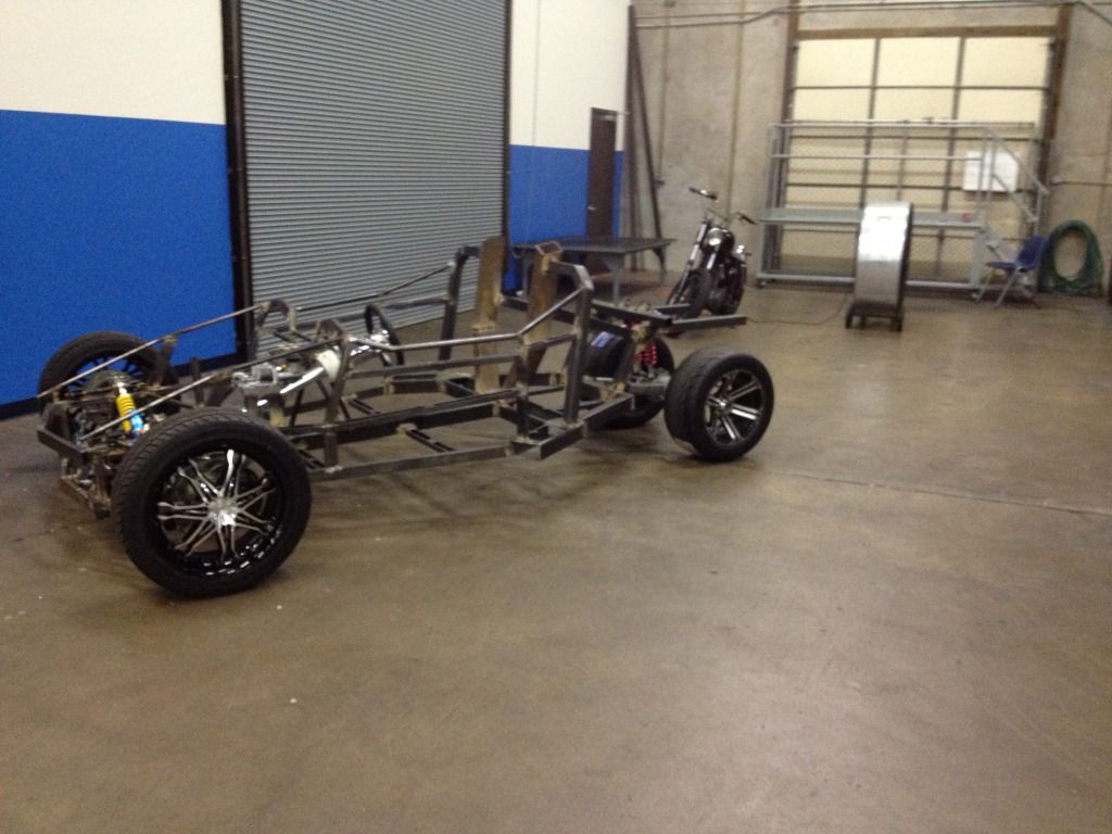 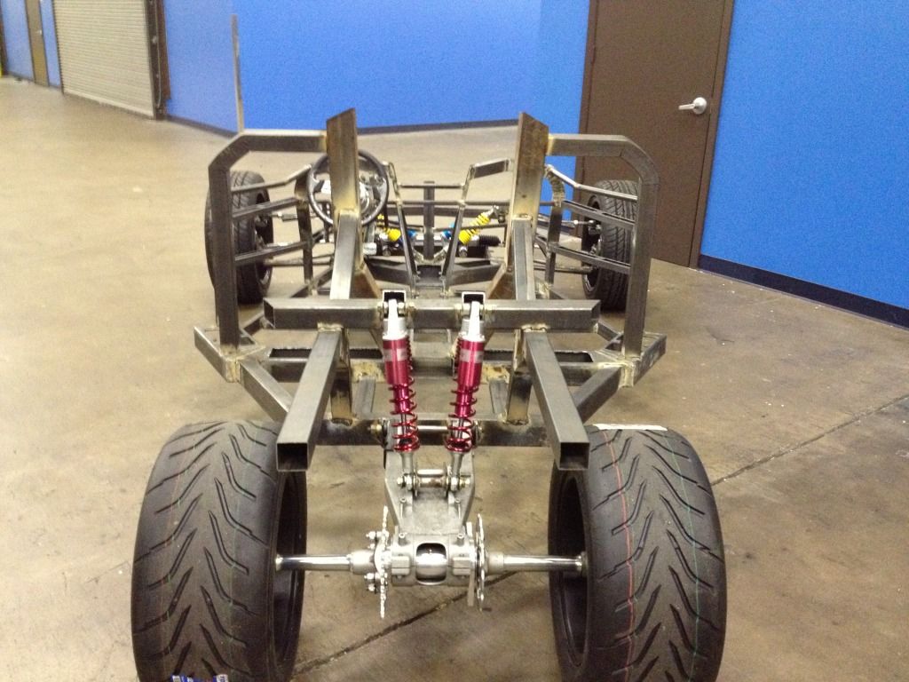 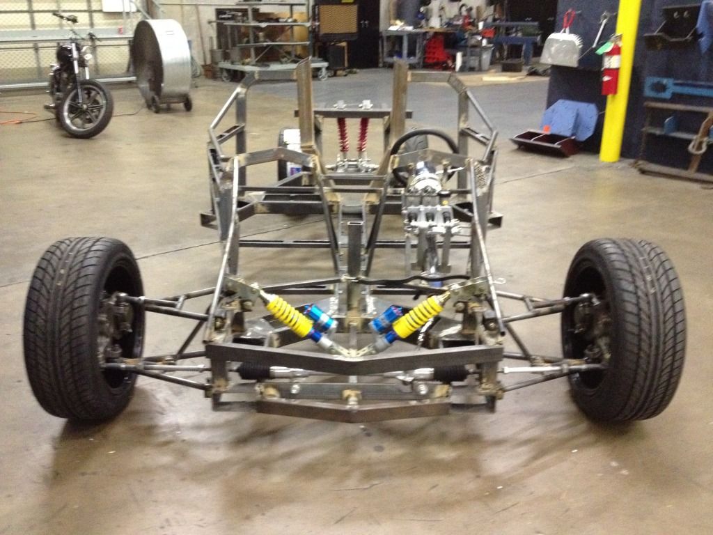 The front needs to still be adjusted a little more but it is pretty close. I also got the ride hieght up in the front to 7" which is a definite plus. Hopefully the engine will be going in it next but I am waiting to see if someone comes through with a wrecked 1300 Huyabusa before I decide on the bandit 1200. I am sure the bandit will be enough but I would love to have the additional HP so I'll give it a week or so. |
|
|
|
Post by mtntech on Jun 19, 2012 22:46:00 GMT -5
You are a busy beaver!! Turbocharging is also an option. Keep the boost low and things are simple.
|
|
|
|
Post by joeld0803 on Jun 20, 2012 16:36:56 GMT -5
Turbocharging the 1200 was a thought because I know you can gain about 50 HP just from doing that without alot of other major engine modifications. I would imagine the carbs would have to be rejetted and the ignition timing recurved a bit.
I may look into that option...........thanks.
|
|
 I read an article regarding the ackerman issue and I now see what is out of sorts.


